 Dellie
The Lab
Dellie
The Lab
Episode 8 of 10 · 27 Sep 2026 · 6 min read
The loose pin
A drawing with its labels backwards, a crashed laptop, and one wire that was never soldered.
Real hardwareOne printed leg, two servos, the servo board and the thumb-sized computer.
Three parts and no picture
On the evening of 27 September I had the printed leg, two hinge halves and a servo on the desk, and no idea how they went together. The AI explained it twice, with boxes and arrows, then with separate drawings of each part. Neither helped:
“Can you show me a normal, human picture of how they snap together? What you’re drawing is useless.”
What worked was a real photo of the finished leg, from the designer’s own page, with the parts pointed out, and then the designer’s own drawing. The rule we wrote down: for how parts fit, show the real object first. Diagrams are for wiring.
The label was backwards
By 20:05 the knee was screwed together, but the 8 mm screw seemed too short. The AI kept explaining from its drawings, now about where the hip part goes, and I stopped it:
“I think you don’t understand what you’re talking about. Check my Downloads folder.”
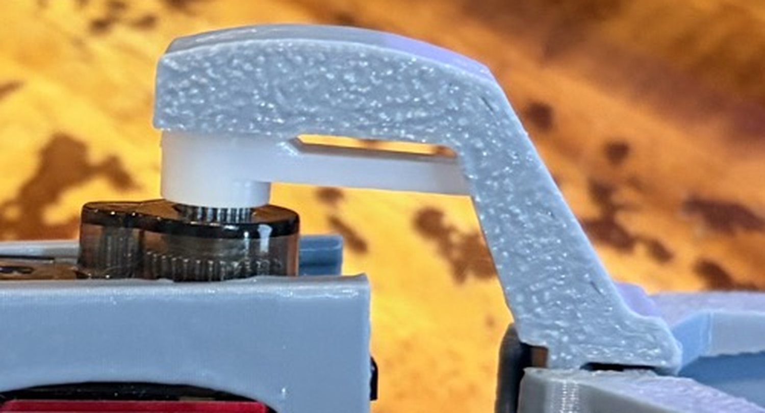
In the folder was my photo of the leg; a close-up of it is at the top of this page. Four minutes later I’d found the real problem with the parts in my hands:
“I used the wrong side. This round recess was for the bump, and the other part was for the propeller. Now the screw goes in the correct way.”
The AI’s drawing had labelled the round cup as the propeller’s side. It belongs on the bump on the other side of the servo box. I’d built it exactly as the drawing said. The screw was always the right length.
A hip from a knee
With the knee done, a part was missing. The leg’s designer mounts the hip servo inside the robot’s body, and we weren’t printing a body yet. Then the AI noticed the two hinge halves are identical. Each one wraps a servo box, so the leg’s own servo box already has the right shape for a hip.
So the AI cut the leg’s 3D file right after its servo box and added a flat tab with two holes. About 15 grams of plastic. It first said the print needed supports, then measured the overhangs and said it didn’t. It printed clean without them, and by 22:06 the whole leg was together.
Then came the bench power supply and its first test (Episode 7). Next, the servo board.
The board that wasn’t there
The servo board needs four wires from the thumb-sized computer: power, ground and two message wires. The usual pins for those two, D4 and D5, had never been soldered. Only D1, D6 and ground had. So we tried D4 and D5 pushed into the breadboard, unsoldered.
At 23:24 the board’s red light was on and the program had uploaded. The board didn’t answer. The program reported it as missing.
A crash
The AI changed the program to ask every possible address and uploaded it to the little board itself, from my laptop, twice in a row. During the second upload, my laptop crashed and restarted.
Kernel data abort (far: 0x0)
Panicked task: arduino-cli
Backtrace: usb.cdc.acm · usb.cdc
           · IOSerialFamily
No servo power was connected, so nothing on the bench was at risk. But a new rule went in: no uploads from the AI without telling me first, one at a time, never back to back. From then on I uploaded from my own screen, with no more crashes that night.
Cut it in half
Then the slow part. Each test below splits what’s left into two halves, and the result says which half the fault is in.
- The board’s light: on. Power reaches it.
- Beep test, laptop unplugged: both message wires connect, pin to board.
- Ask every address, by my own hand: nothing answers. So it isn’t the wrong address.
- Beep between the two message wires: silent. They don’t touch each other.
- Meter on the board, laptop plugged in: power and both message wires rest at 3.3 volts.
- Make the computer flip both wires on and off, once a second: one flips at the board, one never does.
- Move both wires to the soldered pins: the board answers.
The fix needed no soldering iron. The little computer can send its message wires out of almost any pin, so one line in the program moved them to D1 and D6, the two pins that were properly soldered. At 23:53 the board answered: “S found: 0x40”.
It was the third time an unsoldered pin had cost me an evening: 27 August, 5 September, and now this. The rule for the full robot: every pin that carries a signal gets soldered.
Start from the real thing in your hands. Then cut the problem in half until one half is left.
Less than two hours later, the fly moved this leg. That’s Episode 9.