 Dellie
The Lab
Dellie
The Lab
Episode 7 of 10 · 20–28 Sep 2026 · 8 min read
Measure, don’t trust
The label said 5 volts. The meter said 2.8. After that, I said my number before the meter did.
Real hardwareA power bank, a bench power supply, a meter and a servo board.
“OK” is a claim too
On 20 September the thumb-sized board on my desk started taking orders (Episode 6). I typed an angle, and it answered “OK”. But OK only means the board read the command. Whether the shaft turned took my own eyes:
“It did, in the opposite direction from the neutral.”
Right answer: the two angles I typed sit either side of the middle. The board’s word was a claim; what I saw was the measurement. The rest of this episode is the same idea, bigger.
The label said 5 volts
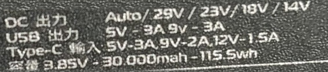
By the end of that night the AA batteries were finished for this build: 3.9 volts under two servos that need 4.8. The next idea was a big power bank, with a label that promises 5 volts at up to 3 amps on USB. Out came the meter.
What the label says
- USB output: 5 volts, up to 3 amps.
- The USB-C port is an input, for charging the bank.
What the bench said
- Only the meter on the wires: 2.8 volts, steady.
- The same wires pushed into a breadboard: 0.6 volts.
- Two servos plugged in: 0.6 volts, and they never moved.
- The USB-C port, “the input”, charged my phone.
Every reading disagreed with the label. And the bank wasn’t simply flat, or it couldn’t have charged my phone.
What the second opinion caught
That night the question went to Grok, another company’s AI that reviews our work. It started bluntly:
“The label’s 5 V / 3 A is a claim; the meter reading is 2.8 V.”
It also caught something the first AI had missed entirely. On a breadboard, five holes in a row are joined underneath. If the red and black wires went into the same row, plus and minus were joined directly, and 0.6 volts is what a short circuit looks like.
And servos were the wrong test load: an MG90S needs about 4.8 volts to start, so at 2.8 it draws almost nothing, and a bank asleep until something draws current would never wake.
The test Grok proposed, one plain resistor across the wires, was never run on the bank. The next day I ordered a bench power supply instead. Why the bank read 2.8 volts is still open.
A test you can’t misread
A bench power supply is a box with two limits: the most volts it may push, and the most current it may let through. Whichever limit is reached first wins. Mine arrived on 23 September. Before it went near the wall socket, I read its back panel: 230 volts ±10%, which covers Vietnam’s 220.
Grok planned its first test: 5 volts, a 0.10-amp limit, a 47-ohm resistor across the clips, then watch the voltage fall. The first AI checked the arithmetic before we ran it. At 5 volts, 47 ohms draws 0.106 amps, just over that limit, so the voltage would only sink to 4.7. A 0.3-volt dip is easy to read as noise.
So the limit went down to 0.05 amps. Now the supply has to hold the current at 50 milliamps, and the voltage must fall to 2.35. Half the voltage: impossible to miss.
27 September: say the number first
The rule on my bench: before the power goes on, I say what the meter will read. A number said out loud can be wrong. A number read afterwards always looks like the one you expected.
It was my first time with a bench supply. The team’s instructions came with a correction from the maker’s manual: set the limits with the Output button off. Three minutes later I read my own front panel. It has no Output button. The first method stood.
Then everything read zero: the voltage knobs were all the way down, so nothing pushed any current. By 22:36 the supply was at 5.00 volts with a 0.05-amp limit, and the meter agreed. The resistor went on with the power off, and I gave my number:
“U = R × I, so 47 × 0.05 (not sure we can define the current, to be honest)… so 2.35 volts.”
The meter read 2.33 volts. And my doubt was the real point of the test: in this mode the current is set, by the current knob. The supply lowers its voltage until exactly that current flows.
Then the other half: turn the current limit up with the resistor still on. I said it would stop at 5 volts and about 0.1 amps. It stopped at 0.107. Worked backwards, both tests give the same resistor, about 46.7 ohms, not the 47 printed on it. Even a resistor’s label is a claim, inside its 5% tolerance.
Said first, then measured
| The test | Said first | Measured |
|---|---|---|
| Power bank, USB‑A | the label5 V | 2.8 V |
| 47 Ω at a 0.05 A limit | me2.35 V | 2.33 V |
| Current limit turned up | me: 5 ÷ 47≈ 0.1 A | 0.107 A |
| Channel 0, the average | the maths0.243 V | 0.242 V |
The stroke that isn’t there
Those zeros had looked odd from the start. At 22:44 I spotted why: one stroke of the supply’s display, the bottom-left one, never lights. Without it, a 6 reads as 5 and an 8 reads as 9.
That matters: 6 volts is the most an MG90S can take. So the rule became: set the voltage by the meter, never by the display. The night’s results stood, because the meter had read the 5 volts itself, and 2.33 across the resistor means the limit really was 0.05 amps.
Finding channel 0 with a meter
Just after midnight it was time to plug the servos into the new servo board. It has 16 sockets and no numbers printed on any of them. Which one is channel 0? Instead of guessing, we measured.
To hold a servo in the middle, the program sends a pulse 1.472 milliseconds long every 20 milliseconds. A meter is too slow to see pulses, so it shows their average. The maths said: 1.472 ÷ 20 × 3.3 volts = 0.243 volts on the right pin.
A display that spots a stuck joint
At 00:38 the supply powered the servo board for the first time. Both servos jumped to the middle and held, and the supply showed 5 milliamps. Five minutes later I moved the hip one degree at a time: the current rose to 15–35 milliamps on each step, then fell back to 5.
That gave me a free stall detector. A free joint falls back to about 5 milliamps. A joint pressing against something won’t. I can spot a stuck leg on the supply without touching it.
A label is a claim. The meter is the fact. Say your number before you look.
Between the supply test and channel 0, almost an hour went on a little computer that couldn’t find the servo board at all. That’s Episode 8.